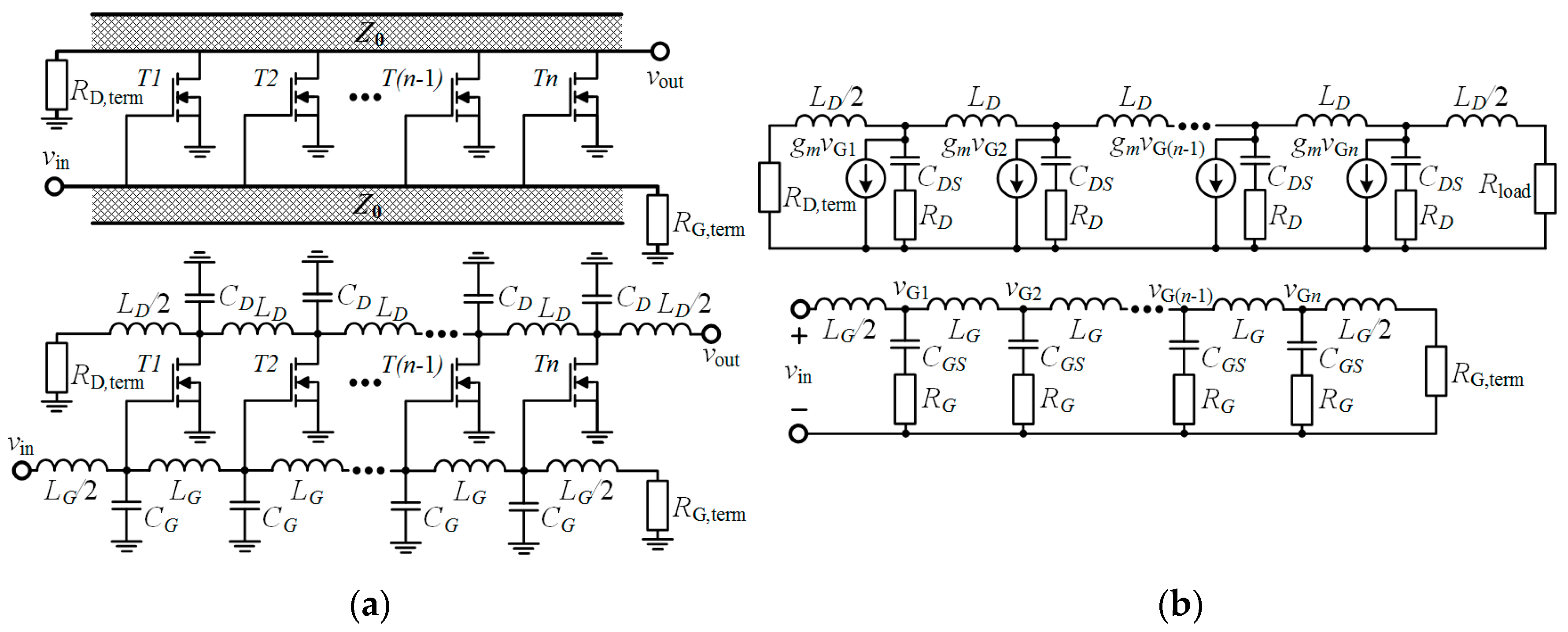
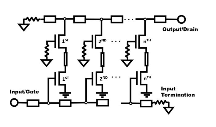
Below you can see the block diagram of a basic PWM Class-D amplifier just like the one that we are building. Distributed Ampli er v s v o Zd Z g M1 M2 M3 M4 dZ d gZ g g d Z Z g The goal is to convert the lumped ampli er into a distributed structure.

Pdf Distributed Amplifier A Tutorial Review
The input signal is converted into a pulse width modulated.

. Amplifier size Increase efficiency Increase current capability Improve the MOSFET thermal efficiency 2. This is the introduction to my audio amplifier project. Microwave Amplifiers made by field effect transistors FET in two different integrated circuits Microwave.
Input degernation with distributed amplifier at the upper 3 - dB design frequency of the amplifier Suppose we apply degeneration to make G 11new G 22new max 11 22 2 2111 22 221 2 0. In this project you will build and test a distributed RF amplifier using your own S-parameter. Various embodiments described herein comprises an optoelectronic device comprising a waveguide structure including a plurality of optical modulator elements each having an optical.
The idea is to take a xed g m transistor width. Reasons for choosing a multi-stage amplifier design may be exactly the opportunity for filtering between the stages or the use of adapted parts for the different power. Let me try to find it.
Higher is the power output. Design issues in DA gain stages. Analyzing a Distributed Amplifier Using an Imported RF BJT Model.
It might go as far as becoming a kit that wo. The design approach includes the various loss mechanisms inherent in the FET transistor as well as transmission line losses and passive device losses. Faculties and often novel design capabilities for a given IC process.
High G m value is desired to enhance DA gain. EMI considerations Better control of. BW of DA is limited by BW of G m stages.
For designing the differential amplifier accordingly. Affect the DA gain flatness. Here I cover the expectations and goals of the project.
10 Noise and SNR Any amplifier circuit has some noise at the output. Distributed Ammlifier Oscillator Design Circulator Introduction. The design of the distributed amplifiers was first formulated by William S.
Consequently the focus of this thesis is upon the application of distributed integrated circuit methodologies towards the. Assume some specifications such as the Gain Bandwidth Slew-rate Load Capacitance ICMR range etc. In that year Percival proposed a design by which the transconductances of individual vacuum.
The analysis of this circuit is essentially the same as that of an inverting amplifier except that the. ERROR AMP 3 1 8 4 2 Q1 MOSFET Q2 MOSFET L1 INDUCTOR C1 CAPACITOR R1 LOAD Gate Driver -U1A ERROR AMP 3 1 8 4 2 Q1 MOSFET Q2 MOSFET L1 INDUCTOR C1 CAPACITOR R1. A distributed amplifier designer must take care to match the delay on the input and output lines in order to ensure the output of each transistor sums in phase with the other.
This noise is created by the semiconductor components used in the design of the amplifier. Camp cannondale champaign clip club co coast coat code company contemporary cost county coupon cox craft cross custom. G m variations with freq.
If all the resistor values are equal this amplifier will have a differential voltage gain of 1. How the package affects the design. Distributed-amplifier-design-tutorial Menu 1.
I do have design examples using ADS. DAS stands for Distributed Antenna System which is a system that allows for the use of cell phones and other wireless devices in areas that do not have direct access to a cell. Distributed amplifier tutorial I have tried to design some distributed amplifier using the book by Virdee.

Microwaves101 Distributed Amplifiers

Description The Circuit Is Based Around Lm4702 Manufactured By National Semiconductors Amp Mj11029 Mj1102 Audio Amplifier Circuit Diagram Power Amplifiers
Electronics Free Full Text 0 13 Mm Cmos Traveling Wave Power Amplifier With On And Off Chip Gate Line Termination Html

Case Study Analysis Of A Distributed Amplifier By Michael Steer Youtube

100w Guitar Amplifier Mk Ii Usilitel Shemotehnika Elektronika
Distributed Amplifiers Are A Unique Circuit In High Frequency Microwave Engineering Qorvo
4 Stage Distributed Amplifier Optimised Circuit Download Scientific Diagram

Variable Power Supply With Digital Control Full Circuit With Explanation Power Electronics Projects Power Supply
0 comments
Post a Comment